The Making of LISA

Warning: I haven't tried to make this understandable to anybody but electrical engineers. Of course, I'm not an electrical engineer myself, but being a hard-core computer geek is fairly close.
I began this project with an Archer 276-1598 "Experimenter's Plug-In Card", which has ground and +5V power runs and thousands of pre-drilled, pre-tinned holes. For about $20 at Radio Shack, this card sure saved me a lot of boring work.
I decided to use the x86 I/O space for the card I/O-- no
DMA, no interrupts. This keeps the card and programming simple.
I decided on the address range 0x120-0x13F, which is probably
enough space (32 bytes) for anything I'll ever want to do.
It also seems unused on most machines.
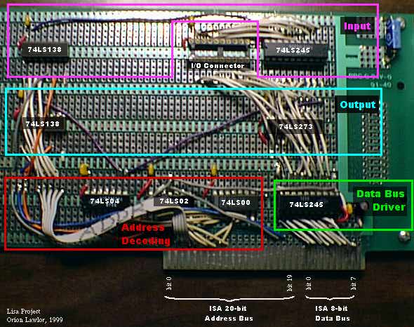
Having decided on an address range, I cranked out a fairly small circuit to do the decoding. The "address enable" line goes high whenever the address bus reads between 0x120 and 0x13F, modulo 0x400. The circuit is implemented using a 74LS00 (quad NAND), 74LS02 (quad NOR), and 74LS04 (hex inverter).
The ISA 8-bit data bus is continually being read, and ocassionally being driven, by the bottom 74LS245 (8-in bus driver). The only time we drive the bus is when IO_Read is active and our address enable is high. This chip drives an on-card data bus, which runs past all the devices on the card.
One input and one output 74LS138 (1-of-8 selector) chip selects which device on the card is to perform input or output. I like the '138 because it has three enables, which eliminates a lot of annoying control logic. I can just run IO_Read into an inverting enable of the input selector, IO_Write into the output selector, and address enable into the non-inverting enables. This leaves one inverting enable, into which I run A3-- this makes only one alias of the enables in my I/O space, instead of three. The low three bits of the address bus get fed straight into the select inputs on each '138. This lets me support 8 Input and 8 Output devices, whithout adding any more control logic!
Despite all this support, I only have 2 I/O chips on the board right now-- one 74LS273 (8-bit latch) provides 8 bits of output, and another 74LS245 (8-bit bus driver) provides 8 bits of input.
I run the input and output lines into a DIP plug-in socket, and from there down a 10 foot 20-conductor flat ribbon cable into the outside world. Once there, support electronics (which I have yet to build) might attach servos to the outputs and contact sensors to the inputs for a robotics project; or attach a solenoid button-pusher to the output and a coffee sensor the input for an automated, accounting coffee machine; or ...
The circuit schematic is:
And a close-up of the card looks like:
LISA was quite a fun project-- we programmers rarely get to use our soldering irons; and even more rarely does the result do anything. The parts definetly totalled to less than $50, but I must have spent at least 15-20 (enjoyable) hours designing, shopping, and soldering. Building custom hardware is a fun, but you need the background and lots of time. 1998/1999 Christmas Break.