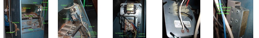
| 1_overview.jpg | 2_electric.jpg | 3_transformer.jpg | 3b_transformer.jpg | 4_relay.jpg |
So we began having furnace trouble shortly before Christmas 2002--we came home to find the house a bit chilly: about 65, rather than the usual 72. Tearing off the cover revealed that the furnace's blower fan (which pulls the heat off the burner and distributes it through the house) was no longer coming on automatically. Luckily, the furnace also has a manual fan control, so we were able to restore largely normal operation by just switching to "Fan On" mode.
It was rather annoying, though, because keeping the blower on all the time results in a drafty-feeling house, wastes energy, and is a constant background noise.
Sadly, the furnace, proudly marked "Janitrol", was installed when the house was built in the early 1950's. The manufacturer, Surface Combustion Corporation, is now an aerospace and defense contractor and, needless to say, has zero information about the furnace on their website. I understand the name "Janitrol" is still being used today, having been sold off in the 1970's.
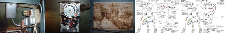
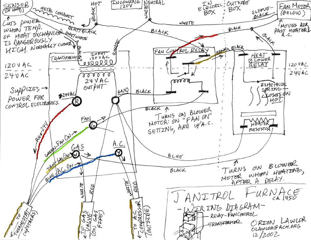
The only information I had was the incredibly ancient wiring diagram in "wiring_ancient"--note how it makes no mention of the air conditioner, which was presumably a late add-on. My Dad has an encyclopediac knowledge of furnaces; but he lives in Alaska, which is the primary reason these pictures even exist.
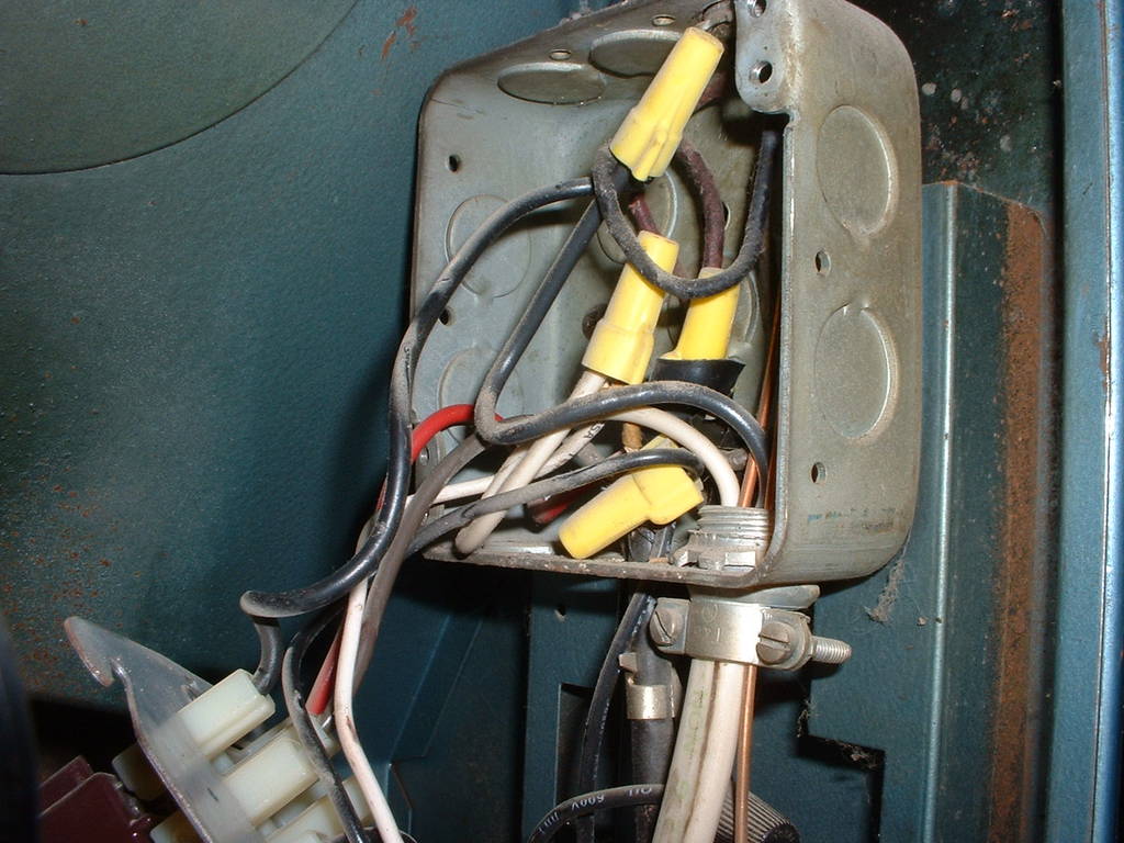
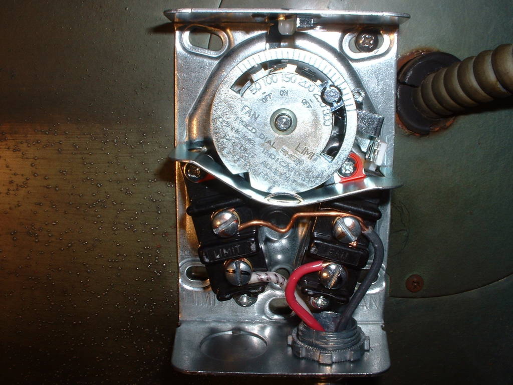
The overall setup is shown in 1_overview: natural gas comes in on the left, is controlled by a gas valve in the center, and flows to burners in the center. Our focus is the bizarre wad of electronics stuffed on the right side, as shown in 2_electric.
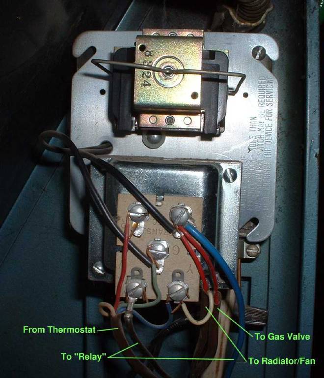
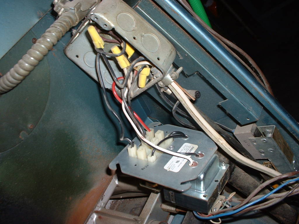
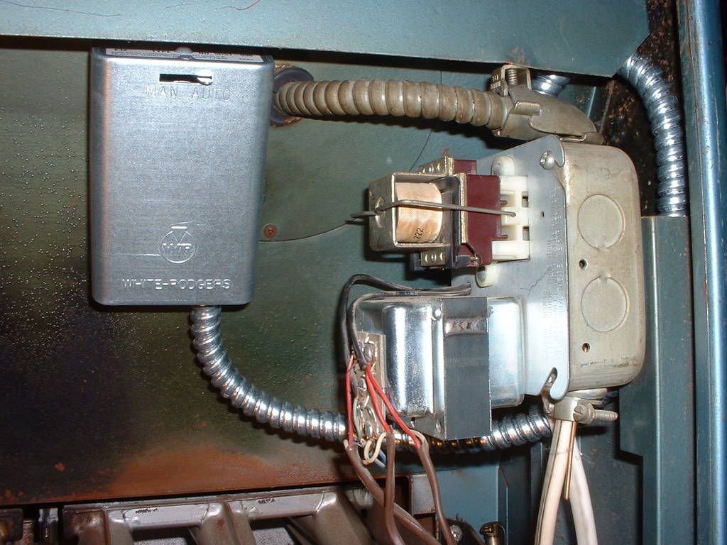
My inferred wiring diagram is shown in wiring_modern. Most of the action is centered around a transformer, shown in 3_transformer and 3b_transformer, that converts 120 volts AC regular wall current (high side) to 24 volts AC (low side) used by the various control mechanisms. Virtually all the control is done at the thermostat, via just 3 output wires: fan override in green, gas request in tan, and air conditioning request in blue. The only input to the thermostat is a 24 volt red wire, and of course the ambient temperature (but there's no wire for that!).
For cooling, the thermostat sends 24 volts down the AC request and fan control lines. The AC request is runs on straight outside to the condensor; but the fan control runs through the little fan control relay shown at the top of 3_transformer.
For heating, the thermostat again initiates the action; but instead of turning on the fan itself, there's a separate switch (marked "relay"? in 2_electric) that's supposed to kick the fan on once the heat exchanger is hot enough. Bizarrely, though, this switch *doesn't* have a temperature sensor on the heat exchanger; instead it watches the gas control line via a little heater resistor which directly closes a bimetallic strip switch. Read that again--rather than measure the burner's temperature directly, this switch has a little *simulated burner* (the heater resistor) which it measures. This is actually pretty similar to what I might do in a control program if I couldn't get a real sensor on the heat exchanger; but it's all done in hardware! I believe this Rube Goldberg-ian monster is the source of my problem--the simulated burner isn't burning, or else the little bimetallic spring sensor isn't sensing. I'll know for sure after I replace the bugger.
Some of the beautiful suprises in the circuit are an "overheating sensor" in the heat exchanger, connected via the heavy metal conduit at the top of 2_electric. The ground for the entire setup is normally run through this sensor. If things get too hot, the sensor cuts the circuit's neutral line, which turns off the entire transformer, including the gas control.
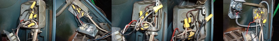
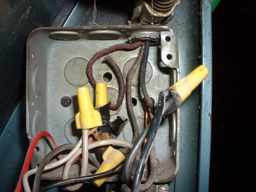
The 120 volt wiring inside the main box is a nightmare--see the horror for yourself in the images labelled 5_guts. In addition to just general tangling, the main blower motor control wire junction is a hideous ball of insulation and electrical tape.
|
| |||||
|
 | |||||
|
 | |||||
|